


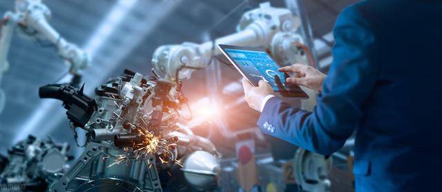
Industrial cameras are a key component of machine vision systems, and their essential function is to convert light signals into ordered electrical signals. Selecting the appropriate camera is also an important aspect of machine vision system design, as the choice of camera not only directly determines image resolution and quality, but also affects the operation of the entire system.
Industrial cameras, also commonly known as cameras, have higher image stability, transmission capacity, and anti-interference ability compared to traditional consumer cameras. Most industrial cameras on the market are based on CCD (Charge Coupled Device) or CMOS (Complementary Metal Oxide Semiconductor) chips.
CCD is currently the most commonly used image sensor in machine vision. It combines photoelectric conversion with charge storage, charge transfer, and signal reading, making it a typical solid-state imaging device. The outstanding feature of CCD is that it uses charge as a signal, unlike other devices that use current or voltage as a signal. This type of imaging device forms a charge packet through photoelectric conversion, and then transfers and amplifies the output image signal under the action of driving pulses. A typical CCD camera consists of an optical lens, timing and synchronization signal generator, vertical driver, and analog/digital signal processing circuit. As a functional device, compared with vacuum tubes, CCD has the advantages of no burn-in, no hysteresis, low voltage operation, and low power consumption.
The development of CMOS image sensors first appeared in the early 1970s. In the early 1990s, with the development of Very Large Scale Integration (VLSI) manufacturing process technology, CMOS image sensors rapidly developed. CMOS image sensors integrate photosensitive element arrays, image signal amplifiers, signal reading circuits, analog-to-digital conversion circuits, image signal processors, and controllers on a single chip, and also have the advantages of programmable random access to local pixels. CMOS image sensors have been widely used in high-resolution and high-speed applications due to their good integration, low power consumption, high-speed transmission, and wide dynamic range.
There are many forms of industrial cameras, and this article will provide a detailed introduction to several commonly used types of industrial cameras.
The difference between area scan cameras and line scan cameras is that the former collects image information based on a two-dimensional plane, allowing for the direct acquisition of complete two-dimensional image information, while the latter collects image information based on a “line,” which is a long, narrow shape with only a few pixels in width because line scan cameras only have one row of photosensitive elements. Although area scan cameras have more pixels in total, the pixels are distributed among each row, so their resolution and scanning frequency are generally lower than those of line scan cameras.
Since the photosensitive elements of line scan cameras are arranged in a “line” shape, the collected image information is also linear. To obtain complete image information, it is often necessary to use scanning motion, such as when capturing images of materials that move uniformly in a straight line, such as metals or fibers. Line scan image sensors are primarily CCD-based, although there have been some line scan CMOS image sensors on the market, line scan CCDs are still mainstream. Currently, the use of TDI CCDs in combination with scanning motion to obtain images is widely used, especially in situations that require a large field of view and high image resolution. Area scan cameras can be used for measuring area, shape, position, or surface quality, and directly acquiring two-dimensional images can to some extent reduce the complexity of image processing algorithms. In practical engineering applications, the appropriate type of camera should be selected based on the requirements of the project.
Black and white cameras and color cameras are easy to understand. If the output image is black and white, it is a black and white camera, and if it is color, it is a color camera. Let’s first look at the simple black and white camera. When light shines on the photosensitive chip, the photon signal is converted into an electron signal. Since the number of photons is proportional to the number of electrons, the main task is to count the number of electrons in order to form a black and white image reflecting the strength of the light. After being processed by the camera’s internal microprocessor, the output is a digital image. In a black and white camera, color information in the light is not preserved.
How to choose an industrial camera
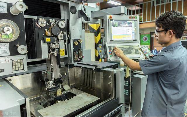
Industrial cameras are usually installed on machine production lines to replace human eyes in measurement and judgment. They capture digital images of the target and convert them into image signals, which are then transmitted to a specialized image processing system. The image system performs various operations on these signals to extract the features of the target, and then controls the equipment on the scene based on the results of the analysis.
X-axis system accuracy (X-axis pixel value) = field of view (X-axis) / CCD chip pixel count (X-axis)
Y-axis system accuracy (Y-axis pixel value) = field of view (Y-axis) / CCD chip pixel count (Y-axis)
Of course, the theoretical pixel value should be determined based on a comprehensive consideration of system accuracy and sub-pixel methods.
System single operation speed = system imaging (including transmission) speed + system detection speed
Although the theoretical calculation of the system imaging (including transmission) speed can be based on the camera’s asynchronous triggering function, shutter speed, and other factors, the best method is to perform actual tests using software.
Matching of video signal: There are two formats for black-and-white analog signal cameras, CCIR and RS170 (EIA), and acquisition cards typically support both types of cameras.
Matching of resolution: Each board only supports cameras within a certain range of resolutions.
Matching of special functions: If you want to use the camera’s special functions, make sure that the acquisition card supports this function. For example, if you want to take pictures with multiple cameras at the same time, the acquisition card must support multiple channels. If the camera is line-scan, the acquisition card must support line-scan.
Matching of interface: Confirm whether the camera and board interface match, such as CameraLink, GIGE, CoxPress, USB3.0, etc.
This passage provides an example of how to choose an industrial camera for a dimension measurement task. The product size is 18mm * 10mm, the required accuracy is 0.01mm, and the detection speed is 10 pieces per second. The working environment is a normal industrial environment, and interference is not considered.
Firstly, since it is a conveyor belt operation, the camera should have a line scan feature for high-speed detection. The field of view can be set to 20mm * 12mm (considering the mechanical positioning error, the field of view is appropriately enlarged compared to the object size). Assuming we can obtain a good image (such as by using backlighting) and our software measurement accuracy can consider 1/2 sub-pixel accuracy, then the required camera resolution is 1000 pixels in one direction (20 / 0.01 / 2 = 1000) and 600 pixels in the other direction (12 / 0.01 / 2 = 600). Therefore, the camera resolution needs to be at least 1000 * 600 pixels, with a frame rate of 10 frames per second. A camera with a resolution of 1024 * 768 pixels and a frame rate of 10 frames per second or higher can be selected (or 1280 * 1024 pixels can also be considered if the software performance and mechanical accuracy are not precise enough).


In modern metal fabrication and precision manufacturing, the metal deburri…

Introduction In modern manufacturing, achieving high-quality surface finis…

In the world of smart manufacturing and industrial robotics, a robotic arm…

The robot tool changer comprises a main buffer actuator that can be tied t…

In today’s era of Industry 4.0 and smart manufacturing, flexibility …
+86 19137105901
Chat online


 Language