


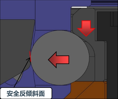
When the robot side of the quick tool changer suddenly loses pressure and the locking mechanism loses the air pressure locking force. The spring will still keep the quick tool changer in the locked position. The tool side of quick tool changer is pulled down by gravity and then driving the steel column to move from the locking slope to the safety opposite side slope. The inclined surface on the opposite side forms an equal neutralizing force to ensure that the tool disc will not fall off.
Fault Self-locking Operation
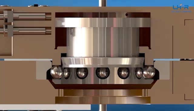
A self-locking state occurs when a malfunction occurs when the locking air pressure of the main disc is unexpectedly lost. When the air pressure is lost, the quick tool changer is loose and there may be a slight separation between the main plate and the tool plate. The lock sensor may indicate that the device is not locked. The failsafe feature utilizes a multi-tapered cam to capture the ball bearings and prevent accidental release of the tool disc. In this fault self-locking condition, the positional accuracy of the tool cannot be maintained.
Do not operate the quick tool changer in a fault self-locking state. If the air source is lost, the exercise should be stopped until the air pressure is restored. After the air pressure is re-established on the main plate, the locking mechanism will energize and securely lock the main plate and tool plate together.
In some cases, when the load on the quick tool changer is significantly off center. It may be necessary to place the load under the quick tool changer or return the tool to the tool storage position to ensure a safe locked state.
If equipped with a lock sensor, ensure that the lock sensor indicates that the quick tool changer is in the locked position before returning to normal operation.
NOTE
Do not use the quick tool changer with a fault self-locking condition. The locking mechanism may be damaged. Before returning to normal operation, re-establish air pressure and make sure the quick tool changer is in the safe locking position.
Unlock Order
1. Place the tool tray in the tool holder so that there is little contact force between the tool tray and the tool holder.
2. Release air from the lock port, then inject compressed air into the unlock port (If equipped, the unlock sensor will indicate the quick tool changer is in the unlock position).
NOTE
Compressed air will cause the locking mechanism to loosen and the weight of the tool tray and attached tool will aid in its removal. If the tool is only released in a vertical position, the weight of the tool helps unlock.
3. Sufficient delay must be set between solenoid advance and robot motion to complete the unlocking process and fully release the tool tray before moving the robot.
4. Move the main plate axially away from the tool plate.
5. In quick tool changer applications, it is recommended to use a tool status sensor in the tool holder to verify that the tool is present and that the tool is still in place when the robot leaves after the unlocking process.


In today’s era of Industry 4.0 and smart manufacturing, flexibility …

In the modern manufacturing landscape, industrial automation is no longer…

In the era of smart manufacturing and industrial automation, the demand fo…

In the rapidly evolving landscape of smart manufacturing, efficiency is t…

When selecting an industrial robot gripper, engineers should evaluate mor…
+86 15333867590
Chat online


 Language